During prototype reviews and mass-production ramp-ups of smartphone camera voice coil motors (VCM), linear resonant actuators (LRA), and micro-motors, engineers often encounter mysterious batch-to-batch quality fluctuations:
- Using identical winding tooling and machine recipes, switching to a new batch of wire causes coil resistance to jump by $5\% \sim 8\%$, leaving the entire lot of motors with inadequate magnetic thrust;
- Wires snap frequently during winding, or lead wires break at the base during light bending, forming, or resistance spot-welding;
- With identical winding parameters, coils wound with Wire A assemble compactly, whereas coils wound with Wire B swell by $0.03\,\text{mm}$ in overall thickness, rubbing against the magnet air-gap;
- Dielectric high-potential (Hi-Pot) sampling tests reveal sporadic, sub-breakdown micro-arcing;
- Self-bonding coils exhibit significant outer diameter springback or loose turns after passing through the thermal curing oven.
Design engineers often focus their troubleshooting on winding machine tension calibration, fixture precision, or dispensing adhesives, overlooking the physical root cause: as the physical vehicle for electro-magnetic energy conversion, the micro-scale enamelled wire itself—and its manufacturing physical history—directly dictates the dimensional tolerances, resistance consistency, thermal endurance, and yield ceiling of the finished coil.
How does an ultra-fine self-bonding wire with a conductor diameter of just $0.040\,\text{mm}$ (and even down to $0.010\,\text{mm}$) transform step-by-step from an $8.0\,\text{mm}$ bulk copper rod? What micro-mechanical and chemical evolutions do its copper crystal grains, base insulation enamel, and outer self-bonding coat undergo along the way?
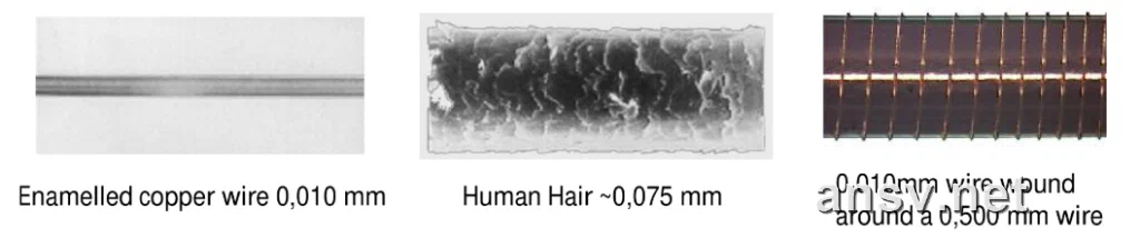 ▲ Figure 1: Dimensional comparison of 0.010 mm (10 μm) ultra-fine enamelled copper wire against a human hair (~0.075 mm) and a 0.500 mm spindle
This section systematically breaks down the entire industrial manufacturing chain of micro-scale magnet wire (specifically bondable air-core magnet wire): from raw copper rod multi-pass drawing and inert protective annealing, to dual-station coating, catalytic curing, surface micro-lubrication, dual-axis laser closed-loop gauging, and servo constant-tension spooling.
1. Fundamental Anatomy and Classification of Magnet Wire
In electromagnetic component manufacturing, insulated wires are broadly categorized into four product families based on their insulation architecture: standard enamelled wire, self-bonding wire, high-frequency Litz wire, and fully insulated wire (FIW).
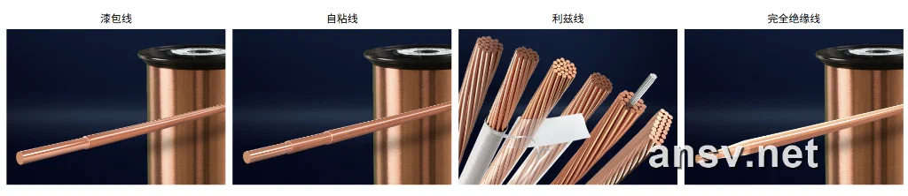 ▲ Figure 2: Cross-sectional architecture of the four major industrial magnet wire families (single-conductor standard enamelled wire, self-bonding wire, stranded Litz wire, and triple-insulated extruded wire)
1. Three Concentric Layers of Self-Bonding Wire
Standard enamelled wire is primarily wound onto plastic bobbins that provide permanent mechanical structural support. In camera VCMs, periscope zoom actuators, and ultra-thin haptic motors, however, squeezing spatial utilization to the absolute physical limit requires bobbinless self-bonding wire (bondable wire).
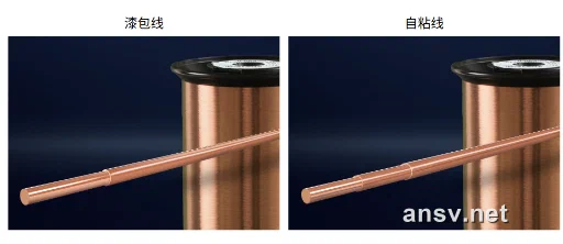 ▲ Figure 3: Physical layer comparison: standard dual-coat enamelled wire (left: conductor + primary insulation) vs. self-bonding wire (right: conductor + primary insulation + outer bond coat)
The cross-section of a self-bonding wire comprises three tightly coupled concentric layers:
- High-Purity Conductor Core:
- Located at the center, typically drawn from Electrolytic Tough Pitch copper (ETP1, Cu $\ge 99.99\%$). It conducts electrical current and generates the Lorentz ampere-turns force;
- Base Insulation Enamel (Base Coat):
- Tightly bonded to the conductor surface with a single-wall thickness of several micrometers. Formulated primarily from polyurethane (UEW) or polyesterimide (EIW), it delivers high dielectric breakdown voltage and inter-turn insulation resistance. Polyurethane enamels possess solderable characteristics (decomposing and vaporizing cleanly in a $360^\circ\text{C} \sim 400^\circ\text{C}$ solder pot), enabling direct soldering without prior mechanical or chemical stripping;
- Outer Bonding Coat (Bond Coat):
- Applied over the base insulation, typically $1.0 \sim 3.0\,\mu\text{m}$ thick. Formulated from modified polyamide (nylon) or epoxy resins. During or immediately after winding, thermal activation (hot air, electric current, oven baking) or solvent exposure causes the bond coat to reflow and fuse with adjacent turns. Upon cooling, it polymerizes into a rigid, self-supporting air-core coil.
2. Conductor Metallurgy and Cross-Sectional Geometry
The metallurgical selection of the conductor core directly governs DC resistance, moving mass inertia, and flexural fatigue endurance under high-speed winding. Physical properties of common conductor alloys for micro actuators are compared below:
| Conductor Category | Material Grade | Density ($\text{g/cm}^3$) | Conductivity (% IACS) | Resistivity ($\Omega\cdot\text{mm}^2/\text{m}$) | Tensile Strength ($\text{MPa}$) | Relative Bending Life (Cu=100%) | Primary Application Scenarios |
|---|---|---|---|---|---|---|---|
| Pure Copper | ETP Copper (ETP1) | $8.93$ | $100\%$ | $0.01724$ | $250$ | $100\%$ | Standard benchmark for general coils, micro motors, consumer electronics |
| Pure Copper | Oxygen-Free Copper (OFC) | $8.93$ | $101\%$ | $0.01693$ | $260$ | $100\%$ | High-end electroacoustics, premium micro actuators, high-frequency Litz wire |
| Copper Alloy | $0.3\%$ Tin-Copper (CuSn) | $8.95$ | $83\%$ | $0.01860$ | $320$ | $1500\%$ | Haptic motors, earphone voice coils, fatigue-resistant flexing leads |
| Copper Alloy | $2\%$ Silver-Copper (CuAg2) | $8.98$ | $86\%$ | $0.01860$ | $340$ | $2800\%$ | Ultra-high-speed winding, high-sensitivity micro voice coils |
| Copper Alloy | $4\%$ Silver-Copper (CuAg4) | $9.01$ | $81\%$ | $0.01760$ | $380$ | $3600\%$ | Ultra-fine diameters ($<0.035\text{mm}$), aerospace and high-reliability drives |
| Lightweight | Copper-Clad Aluminum (CCAW-15%) | $3.63$ | $68\%$ | — | $180$ | $80\%$ | Loudspeaker/receiver voice coils, high-frequency inertia reduction |
- Conductor Geometries:
- Traditional Round Wire: Highest manufacturing maturity and omnidirectional winding symmetry. However, geometric triangular voids are unavoidable during spatial packing, yielding a practical slot fill factor of only $\sim 76\%$ (theoretical HCP limit $\sim 90.7\%$);
- Rectangular Flat Wire: Possesses a rectangular cross-section that eliminates interstitial voids, pushing slot fill factors to $85\% \sim 95\%$. In micro-scale applications, however, flat wire is constrained by width-to-thickness aspect ratios;
- Micro Square Wire: An engineering milestone breaking through the historical IEC 60317-0-2 lower aspect ratio limit of $1.41$, driving aspect ratios down to $1.0$ (true square wire). Square wire combines the rotational winding ease of round wire with the packing density of flat wire, lifting fill factors to $\sim 90\%$ for ultra-compact actuators.
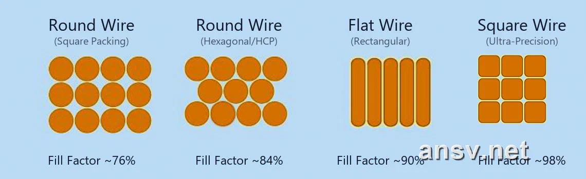 ▲ Figure 4: Cross-sectional stacking comparison and slot fill factor benchmarks: round wire vs. flat wire vs. square wire
3. Thermal Endurance Classes (IEC 60317 Framework)
The thermal endurance class quantifies the capability of the insulation layer to withstand long-term thermal degradation (rated based on a 20,000-hour continuous operating lifespan):
| Thermal Class | Rated Temp | Typical Enamel Chemistry | Insulation Characteristics & Solderability | Typical Applications |
|---|---|---|---|---|
| Class 130 (Grade B) | $130^\circ\text{C}$ | Modified Polyurethane (UEW) | Direct soldering at $\sim 360^\circ\text{C}$, low dielectric loss factor | General consumer electronics, miniature inductors, transformers |
| Class 155 (Grade F) | $155^\circ\text{C}$ | Polyurethane Composite (155-UEW) | Direct soldering at $\sim 390^\circ\text{C}$, balanced thermal and solder reliability | Smartphone camera VCMs, linear resonant haptic actuators |
| Class 180 (Grade H) | $180^\circ\text{C}$ | Polyesterimide (EIW) / PU-Polyamide | Soldering at $\ge 400^\circ\text{C}$, strong thermal softening breakdown resistance | Automotive micro actuators, periscope telephoto drives, high-temp duty |
| Class 200 (Grade N) | $200^\circ\text{C}$ | Modified THEIC Polyesterimide / PAI | Requires laser or mechanical stripping, superior refrigerant & chemical resistance | Industrial control motors, automotive solenoid valves, sensors |
| Class 220 (Grade C) | $220^\circ\text{C}$ | Polyamide-imide (PAI) / Polyimide (PI) | Non-solderable (mechanical/laser strip required), extreme thermal/radiation resistance | Aerospace instrumentation, ultra-high-temp industrial drives |
2. Mechanical Wire Drawing: Plastic Evolution from 8mm Rod to Micron-Scale Conductor
The metallurgical origin of any ultra-fine enamelled wire is a multi-ton coil of continuously cast, high-purity electrolytic tough pitch copper rod (ETP1) with a nominal diameter of $8.0\,\text{mm}$ (or $5/16\,\text{inch}$).
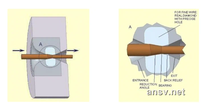 ▲ Figure 5: Precision drawing die functional zones (entrance lubrication, reduction cone, bearing sizing zone, and exit relief)
1. Multi-Stage Cascaded Drawing and Conservation of Volume
Reducing a rod from $8.0\,\text{mm}$ down to a micro-scale wire (such as $0.040\,\text{mm}$ for smartphone VCMs) represents a 200-fold reduction in diameter. Such drastic plastic reduction cannot occur in a single machine; it is cascaded across rod breakdown machines (8mm $\rightarrow$ 2.5mm), medium-wire drawing machines (2.5mm $\rightarrow$ 0.8mm), fine-wire machines (0.8mm $\rightarrow$ 0.15mm), and ultra-fine drawing machines (0.15mm $\rightarrow$ 0.020mm).
As the wire passes through series of progressively smaller drawing dies at speeds up to dozens of meters per second, plastic deformation strictly obeys the conservation of volume:
$$V = \frac{\pi}{4} D_1^2 \cdot L_1 = \frac{\pi}{4} D_2^2 \cdot L_2 \implies L_2 = L_1 \cdot \left(\frac{D_1}{D_2}\right)^2$$Example: A single 1-meter length of $8.0\,\text{mm}$ copper rod extends into an astonishing 40,000 meters (40 km) of $0.040\,\text{mm}$ bare copper wire!
2. Four Functional Zones of a Drawing Die
The drawing die dictates bare copper surface roughness, circularity, and diameter tolerances. A high-precision die incorporates four distinct functional geometric zones:
- Entrance and Lubricating Cone: A wide-angle flare that guides and pressurizes synthetic drawing lubricant, ensuring a continuous hydrodynamic lubricating film coats the copper surface;
- Reduction Cone: Tapered at an angle between $12^\circ \sim 18^\circ$, where the copper experiences intense radial compressive and axial tensile stresses, undergoing primary plastic area reduction;
- Bearing / Sizing Zone: A cylindrical bore strictly parallel to the axis with a length typically $0.3 \sim 0.5$ times the wire diameter. It sets the final wire diameter, circularity, and surface polish;
- Back Relief Zone: Provides clearance to prevent the exiting wire from grazing or scratching against sharp die edges during transverse vibration.
3. Three-Tier Die Material Selection and Maintenance
Die hardness and wear resistance determine diameter drift and roundness over production runs spanning hundreds of kilometers:
- Heavy Rod Breakdown ($> 5.0\,\text{mm}$): Hard metal dies (tungsten carbide) designed to absorb heavy mechanical shock loads;
- Intermediate Diameters ($0.60\,\text{mm} \sim 5.0\,\text{mm}$): Synthetic polycrystalline diamond dies (PCD), balancing extreme hardness with uniform wear;
- Ultra-Fine Diameters ($< 0.60\,\text{mm}$ down to $0.010\,\text{mm}$): Natural single-crystal diamond dies (Natural Diamond, ND) are mandatory. Synthetic diamonds contain microscopic grain boundaries that can cause micro-grooving under high-speed fine-wire friction. Natural single-crystal diamonds can be polished to an atomic mirror finish, eliminating microscopic striations and tightening diameter tolerance bands to $\le \pm 0.0005\,\text{mm}$ ($\pm 0.5\,\mu\text{m}$).
For precision square and flat wires, the chief technical challenge lies in controlling corner blend radii (down to $0.020\,\text{mm}$) to prevent sharp corners from thinning the subsequent liquid enamel coat via surface tension.
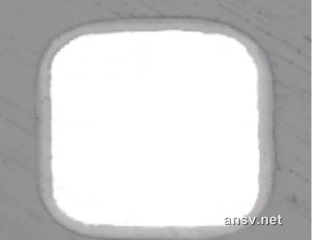 ▲ Figure 6: Metallographic cross-sections of micro self-bonding flat wire ($0.112 \times 0.153\,\text{mm}$) and square wire ($0.07 \times 0.07\,\text{mm}$)
4. Work Hardening and Internal Stress
Under severe multi-pass cold plastic deformation, copper crystal grains experience heavy shear slip along the drawing axis. Equiaxed grains are sheared into densely packed fibrous ribbons, causing dislocation density to multiply by several orders of magnitude:
- Mechanical Property Evolution: The metal undergoes severe work hardening, doubling its tensile strength while fracture elongation drops catastrophically from an initial $35\%$ to under $1\%$;
- Engineering Impact: The bare copper wire becomes extremely brittle and springy, retaining high internal residual stresses. Subjecting the wire to winding tension or tight bending in this state causes immediate brittle fracture. Therefore, drawn wire must undergo annealing to restore plasticity.
3. Stress Relief: Protective Atmosphere Continuous Annealing
To restore ductility and flexibility, the drawn wire passes through an in-line continuous annealing furnace.
1. Dynamic Recrystallization and Grain Reorganization
Annealing employs electrical resistance contact heating or radiant tube heating to elevate the traveling wire above its dynamic recrystallization temperature ($450^\circ\text{C} \sim 550^\circ\text{C}$, matched to speed and diameter):
- Microstructural Reorganization: Thermally activated recrystallization dissolves distorted fibrous grain structures. Strain-free, equiaxed microscopic copper grains nucleate and grow;
- Restoration of Ductility: Tensile strength moderates, while elongation at break recovers to $15\% \sim 25\%$ (fine wire benchmark). The wire achieves supple flexibility, capable of surviving tight corner bends on high-speed winding needles without snapping.
2. Inert Protective Atmosphere Against Surface Oxidation
At $500^\circ\text{C}$, clean copper surfaces oxidize instantaneously upon exposure to oxygen, forming brittle oxide films ($\text{CuO}$ and $\text{Cu}_2\text{O}$) that trigger two fatal failure modes:
- Loss of Conductive Cross-Section: Copper oxides act as semi-insulators, shrinking the effective conductive area and causing finished coil resistance to test high;
- Loss of Enamel Adhesion (Delamination): Loose oxide layers prevent base enamel from forming chemical bonds with the copper substrate. During subsequent winding or pin bending, the enamel flakes off like dry skin, leading to inter-turn short circuits.
Consequently, annealing must occur inside sealed tubes flooded with high-purity nitrogen ($\text{N}_2$) or steam/reducing protective gases, followed immediately by an airtight water quench to ensure pristine, mirror-like copper enters the coating station.
4. Insulation Coating Process: Multi-Pass Thin Application and Curing Control
Enamel application involves liquid polymer spreading followed by thermal cross-linking. Modern magnet wire manufacturing adheres strictly to one governing law: insulation must never be applied in a single thick coat; it requires a disciplined cycle of “thin coats across multiple passes with intermediate baking”.
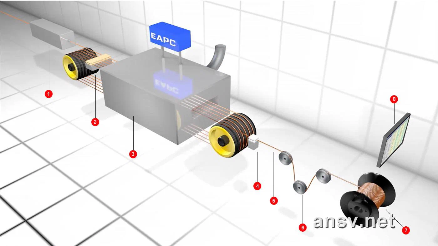 ▲ Figure 7: Industrial vertical multi-pass enamelling, curing, cooling, and spooling line
1. Coating Application: Felt vs. Die Enamelling
- Felt Enamelling:
Used exclusively for ultra-fine wires with diameters below $0.080\,\text{mm}$. The bare wire passes through precision felt pads soaked with liquid enamel, using capillary pressure to meter the wet film. Its chief advantage is near-zero mechanical tension, preventing stretching or necking of fragile micro-conductors; - Die Enamelling:
Used for heavier gauges. Wire passes through tungsten carbide or PCD dies with microscopic clearances that meter and concentricize the wet enamel coat.
2. Why Cycle Through 10 to 25 Passes?
Building a single-side insulation thickness of merely $4\,\mu\text{m}$ is broken down into 12 to 20 successive coating and baking cycles, each pass laying down a microscopic wet film of only $0.2 \sim 0.3\,\mu\text{m}$:
- Preventing Solvent Boiling and Pinholes:
Liquid enamel contains $60\% \sim 70\%$ organic solvents (cresol, xylene). In a thick coating, high furnace temperatures skin-cure the outer surface first, trapping solvent vapors beneath. As vapor pressure builds, it ruptures through the skin, forming craters and pinholes. Thin micro-coats allow solvent molecules to flash off cleanly in fractions of a second; - Statistical Defect Elimination:
Even if an isolated micro-void occurs during one pass, subsequent cross-linked coats overlap and seal the defect, driving the pinhole probability over tens of kilometers of wire to near zero.
3. Curing Furnace Temperature Profiles and Catalytic Combustion
Wet-coated wire rises vertically into a multi-meter curing tower equipped with a steep gradient profile (entry zone $\sim 250^\circ\text{C}$, mid zone $\sim 380^\circ\text{C}$, top zone $450^\circ\text{C} \sim 500^\circ\text{C}$):
- Solvent Evaporation and Catalytic Incineration: Flashed solvents are routed through catalytic combustion chambers where noble-metal catalysts convert volatile organics into $\text{CO}_2$ and water vapor, recirculating clean thermal energy back into the oven;
- Polymer Cross-Linking: Polyurethane prepolymers undergo three-dimensional cross-linking into a resilient, insoluble thermoset film;
- Curing Windows (Under-Cured vs. Over-Cured):
- Under-Cured (oven too cool or wire speed too fast): Incomplete molecular cross-linking leaves residual solvent trapped inside. The enamel exhibits poor mechanical abrasion resistance, weak solvent resistance, and flakes off during winding;
- Over-Cured (oven too hot or residence time too long): Thermal-oxidative degradation embrittles the polymer chains. When bent around tight winding corners, the enamel micro-cracks, causing Hi-Pot dielectric breakdown.
5. Self-Bonding Coating Process: Dual Applicators and Air-Core Coil Bonding
The production of self-bonding wire mirrors standard enamelled wire, but with one fundamental structural difference: the number of independent coating applicators. Standard wire uses a single coating circuit, whereas bondable wire requires two fully independent coating and baking lines arranged in tandem.
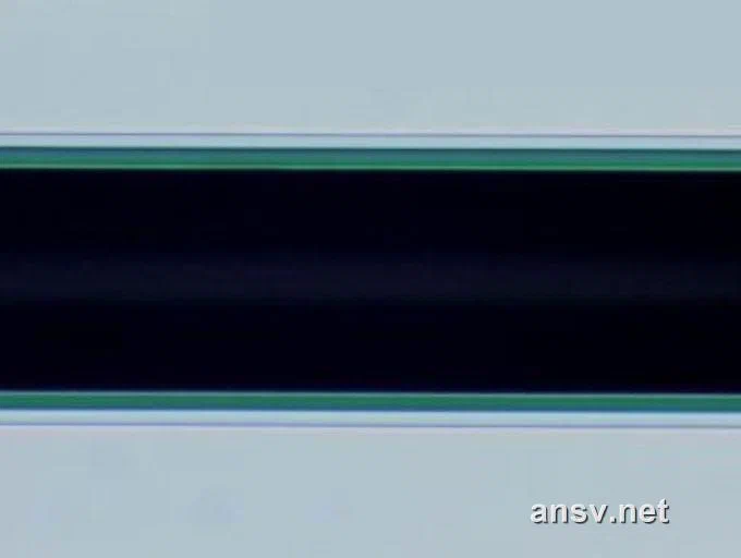 ▲ Figure 8: Microscopic backlight cross-section of self-bonding wire (darker outer ring represents the bond coat)
1. Functional Division Across Dual Coating Stations
- First Applicator (Primary Insulation): Applies 10 to 15 passes of base enamel (such as polyurethane) to establish dielectric withstand voltage and thermal endurance;
- Second Applicator (Outer Bond Coat): Without spooling, the insulated wire immediately enters a second independent coating applicator to receive 2 to 6 coats of bonding resin, followed by a secondary low-temperature curing tunnel.
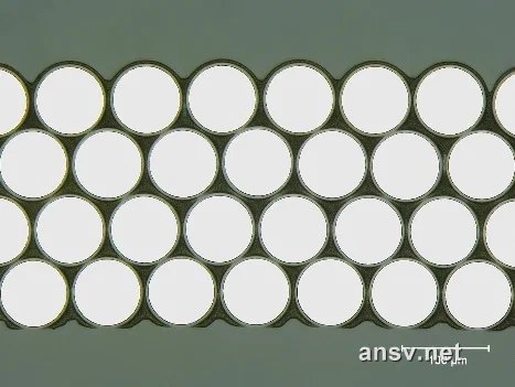 ▲ Figure 9: Metallographic micrograph of cured close-packed self-bonding coil (bright rings: base enamel; dark interconnected matrix: reflowed bond coat; scale bar: 100 μm)
2. Standard Enamelled Wire vs. Self-Bonding Wire Comparison
| Feature | Standard Enamelled Wire | Self-Bonding Wire (Bondable Wire) |
|---|---|---|
| Cross-Sectional Layers | 2 Layers: Copper Core $+$ Base Enamel | 3 Layers: Copper Core $+$ Base Enamel $+$ Outer Bond Coat |
| Winding Mechanics | Requires plastic bobbin or structural former | Bobbinless: Formed and cured directly into a rigid air-core coil |
| Fixing Auxiliary Materials | Requires taping, epoxy potting, or varnish dipping | Zero Auxiliaries: Turns fuse directly to one another during curing |
| Space Utilization & Wall Thickness | Bobbin wall ($0.15 \sim 0.3\,\text{mm}$) robs magnetic air-gap space | Ultra-Thin: Zero bobbin wall, pushing magnetic flux utilization to limits |
| Geometric Freedom | Restricted to injection-molded bobbin shapes | Heated and molded into racetrack, rectangular, polygonal, or custom shapes |
| Total Assembly Cost | Lower wire unit cost, but higher assembly and potting labor | Slightly higher wire cost, but eliminates bobbin and potting steps |
| Target Applications | Transformers, AC contactors, general industrial motors | Smartphone VCMs, periscope actuators, haptic LRAs, wireless charging |
3. Thermoplastic vs. Thermosetting Bonding Chemistries
Outer self-bonding formulations are divided into two chemical families:
- Thermoplastic Bonding:
- Formulated from soluble copolyamide (nylon) resins;
- Re-softening Capability: Melts and flows when heated to its activation point ($130^\circ\text{C} \sim 160^\circ\text{C}$), bonding turns together upon cooling. It can be re-softened by re-heating, allowing engineers to re-press, flatten, or reshape cured coils;
- Thermosetting Bonding:
- Formulated from epoxy resins and blocked cross-linking agents;
- Irreversible Cross-Linking: Heat triggers irreversible chemical cross-linking into a rigid 3D thermoset polymer. Once cured, it will not melt or flow even under temperatures of $180^\circ\text{C} \sim 200^\circ\text{C}$, providing exceptional high-temperature shear strength for high-power haptic actuators and automotive solenoids.
6. Precision Finishing: Lubrication, Laser Gauging & Servo Spooling
Before winding onto shipping spools, finished self-bonding wire undergoes three final quality-control operations:
1. Surface Micro-Lubrication
Wire surfaces receive a precisely metered microgram-level coating of synthetic paraffin wax or specialized lubricant:
- Friction Coefficient Control: Depresses the dynamic friction coefficient into the $0.08 \sim 0.12$ band;
- High-Speed Anti-Scuffing: In high-speed winding machines ($8,000 \sim 15,000\,\text{RPM}$), wire travels through winding nozzles at high velocity. Controlled lubrication prevents enamel scuffing while allowing adjacent turns to slide smoothly into mold corners without bridging or crossovers.
2. Dual-Axis Laser Gauging & High Voltage Continuity (HVC) Monitoring
Modern high-speed vertical enamelling lines integrate online inspection instrumentation:
- Dual-Axis Laser Micrometers: Sample the wire thousands of times per second across $0^\circ$ and $90^\circ$ orthogonal planes, tracking outer diameter, film build, and circularity to maintain concentricity ratios (minimum-to-maximum film thickness) above $>0.75$;
- Inline HVC Spark Testing (IEC 60851-5): Wire passes continuously over high-voltage contact wheels ($500\,\text{V}$ test voltage) to detect sub-micron insulation flaws in real time, triggering automatic alarms and ensuring pinhole defect rates stay below $0.05$ flaws per $30\,\text{meters}$;
- Computer-Integrated Process Control (EAPC): Advanced facilities network draw benches, laser gauges, HVC testers, annealing furnaces, and spooling drives into central SCADA networks (such as Elektrisola EAPC systems). Closed-loop sensor feedback fine-tunes pump metering and capstan speed while generating lot-specific CPK reports.
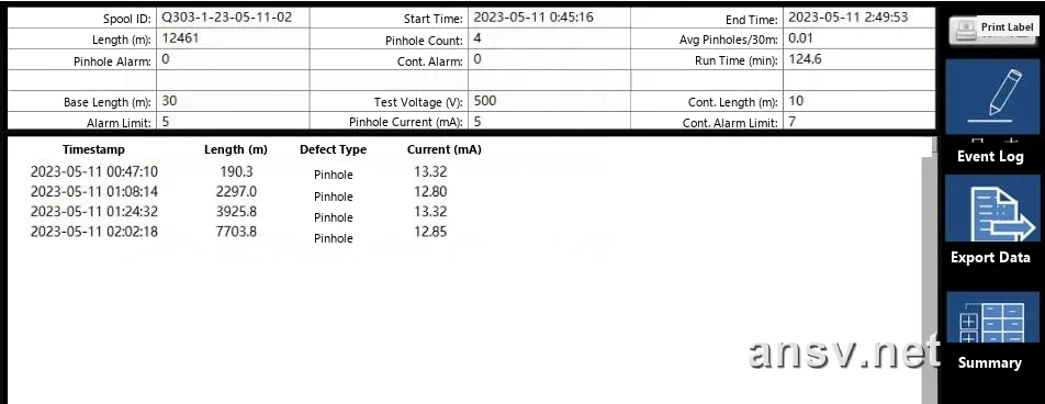 ▲ Figure 10: In-line HVC spark testing log tracking defect-free continuity at 500 V across multi-kilometer spools
3. Precision Servo Tension Control and Spooling
- Constant Tension Control: As spool diameter builds from empty core to full flange, load-cell sensors provide feedback to adjust spindle motor torque, preventing excessive winding tension from elongating and thinning the wire (which would cause high resistance and work-hardening embrittlement);
- Electronic Cam Traverse (Spooling): Traverse guide oscillation is synchronized with spool rotation via electronic gearing algorithms, laying down smooth, parallel wire layers free of trapped turns or wire tangling.
📋 Shop-Floor Inspection Matrix: Incoming QA for Self-Bonding Wire
When inspecting self-bonding wire samples for micro actuator (VCM/LRA) development, execute the following validation matrix:
| Key Inspection Metric | Recommended Standard & Tolerance | Root Cause of Manufacturer Flaw | Assembly Impact on Finished Coil |
|---|---|---|---|
| Bare Conductor Diameter | $0.040\,\text{mm} \pm 0.001\,\text{mm}$ ($\pm 2.5\%$) | Diamond die wear or excessive spooling tension | Finished coil DCR tests high, inadequate motor thrust |
| Maximum Outer Diameter | Grade 1: Conductor $+ 2 \times$ (Enamel $+$ Bond Coat) | Metering pump pressure drift or loose felt tension | Coil swells in thickness, rubbing against magnet air-gap |
| Elongation at Break | $0.040\,\text{mm}$ wire requires $\ge 14\% \sim 18\%$ | Annealing furnace under-temp or surface oxidation | Frequent wire breaks during winding, brittle lead wire snaps |
| Hot Bond Strength | Measured via helical coil twist or push-out test | Inadequate resin cross-linking or shifting oven window | Straight sides sag inward, turns delaminate at high temp |
| High-Voltage Saline Pinhole | Saltwater continuity check, $\le 3\,\text{pinholes} / 10\,\text{m}$ | Inadequate coating passes or rapid oven heating blistering | Inter-turn micro-shorts and dielectric breakdown |
| Dynamic Friction ($\mu$) | Metered surface wax application, $\mu = 0.08 \sim 0.12$ | Uneven lubrication or evaporated paraffin | Nozzle overheating, scuffed enamel, erratic turn stacking |
7. Summary: Material Metallurgy Governs Coil Design Ceilings
Reviewing the physical manufacturing chain of micro-scale magnet wire reveals three immutable engineering principles:
- Copper Ductility Stems from Dynamic Recrystallization: Reducing an $8\,\text{mm}$ rod to tens of micrometers tears metal grains apart thousands of times over. High-purity ETP1 copper and oxygen-free inert annealing form the indispensable bedrock preventing wire breakage and oxidation;
- Sub-Micron Insulation Relies on Multi-Pass Thin Coats: A flawless enamel coating requires over a dozen ultra-thin coating and curing cycles. Slight drifts in oven airflow or temperature translate directly into adhesion flaking or pinholes;
- Self-Bonding Coils Represent Dual-System Composites: Base insulation delivers electrical isolation, while the outer bond coat provides bobbinless structural rigidity. Understanding the melting, flowing, and cross-linking kinetics of thermoplastic and thermosetting bond coats is vital to resolving coil baking distortion and thermal failures.
In the next chapter, 1.2 Why Do Self-Bonding Coils Deform After Curing? Bonding Activation Kinetics & DFM Deformation Control , we dissect the micro-scale fluid kinetics of hot-air and oven bonding, analyzing why coils bow inward and spring back upon cooling.
📚 References & Acknowledgments
- 📄 Technical References:
- We gratefully acknowledge technical documentation and application data provided by ELEKTRISOLA and HUAYE Magnet Wire.
- 🔙 Handbook Navigation: Precision Coil & Electromagnetic Drive Design Handbook Table of Contents
Citation and Technical Discussion Notice
Author: Tony Chen | Digital R&D Expert in Micro Electromagnetic Actuators
Original source: ansv.net
Article URL: https://ansv.net/en/knowledge-base/precision-coil/01-wire-drawing-annealing-and-enameling/
Copyright: Unless otherwise stated, this article's original text, formulas, and original illustrations are licensed under CC BY-NC-ND 4.0 (Attribution—NonCommercial—NoDerivatives). Non-commercial sharing is welcome with attribution and a link to the original; adaptation, alteration, or excerpting is not permitted.
Unless expressly stated otherwise, third-party trademarks, patent figures, product images, and other third-party materials are not covered by this CC license. Their rights remain with their respective owners.
For technical inquiries or discussion, feel free to contact [email protected].
💬 Discussion & Feedback
[email protected]) to automatically load your avatar without logging in.