Micro Voice Coil Motors (VCM) and Optical Image Stabilization (OIS) actuators in smartphone camera modules represent some of the most sophisticated precision servo mechanisms in modern micro-electromechanical systems (MEMS) and micro direct-drive engineering.
Unlike Linear Resonant Actuators (LRA) designed solely for steady-state tactile vibration around a fixed resonance frequency, a camera VCM linear motor must achieve sub-micron positioning ($\pm 1 \sim 2\,\mu\text{m}$) across a travel range of $0 \sim 300\,\mu\text{m}$, while simultaneously canceling hand tremor at $1 \sim 15\,\text{Hz}$ with minimal phase lag for OIS. It is not merely an on-off solenoid, but a finely tuned direct-drive system coupling mechanical structures and materials (Mechanics), air-gap magnetic circuits and coil electrodynamics (Electromagnetics), and closed-loop feedback and feedforward vibration suppression algorithms (Control).
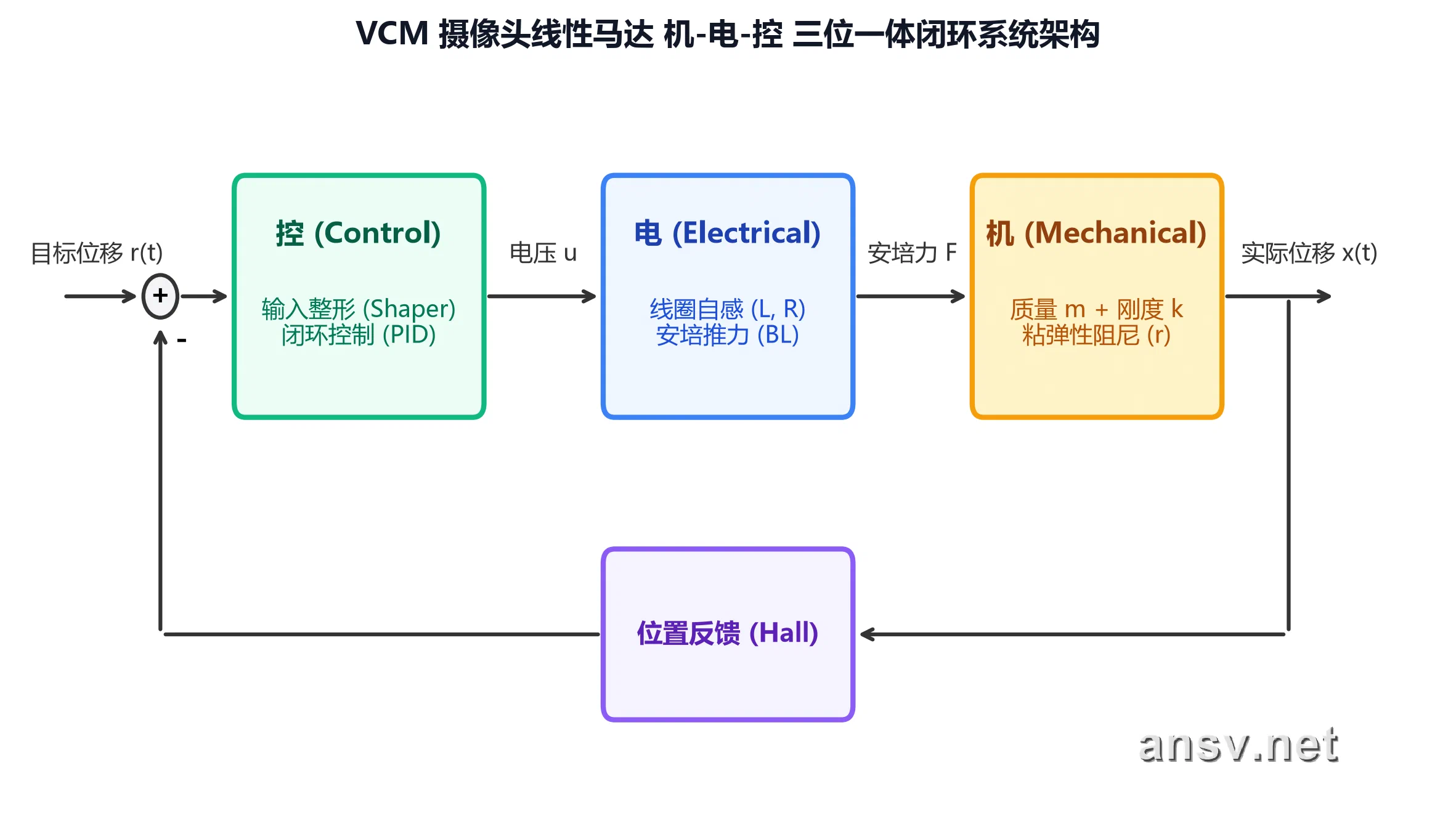
This handbook systematically deconstructs VCM actuators from fundamental 2nd-order physical modeling, material selection, and damping quantification to frequency-domain Bode diagnostics, closed-loop stability margin (GM/PM) safety thresholds, and advanced feedforward vibration cancellation.
⚡ Core Physical & Dynamical Equations
The design and simulation of a micro voice coil motor relies on solving a mechanically, electrically, and magnetically coupled lumped-parameter system:
1. Mechanical Dynamics Balance Equation (Newton’s Second Law)
$$m \frac{d^2x(t)}{dt^2} + r \frac{dx(t)}{dt} + k x(t) = F_{\text{drive}}(t) - G \sin(\theta)$$- $m$: Total moving mass (carrier frame plus lens group, $\text{kg}$ or $\text{g}$)
- $r$: Viscous damping constant (provided by damping glue shear and air drag, $\text{N}\cdot\text{s/m}$)
- $k$: Equivalent spring stiffness of the etched leaf springs ($\text{N/m}$ or $\text{mN/}\mu\text{m}$)
- $G \sin(\theta)$: Axial gravity component depending on smartphone shooting attitude $\theta$
2. Ampere Thrust Force & Electromechanical Energy Conversion
When the coil conductor is orthogonal ($\alpha = 90^\circ$) to the air-gap magnetic flux lines:
$$F_{\text{drive}}(t) = K_f \cdot I(t) = (B \cdot L) \cdot I(t)$$- $BL$ (or $K_f$): Thrust Sensitivity (force constant), representing thrust generated per unit driving current ($\text{mN/mA}$ or $\text{N/A}$)
- $B$: Average magnetic flux density in the effective working air-gap ($\text{T}$)
- $L$: Total effective length of coil wire cutting through the magnetic field ($\text{m}$)
3. Steady-State Equilibrium & Displacement Sensitivity
At steady-state focus ($\dot{x}=0, \ddot{x}=0$):
$$BL \cdot I = k \cdot x \implies x_{\text{steady}} = \left(\frac{BL}{k}\right) \cdot I$$- $\frac{BL}{k}$: Displacement Sensitivity ($\mu\text{m/mA}$), the ratio of electromechanical efficiency to suspension stiffness.
4. Natural Resonance Frequency, Damping Rate, and Quality Factor
$$f_0 = \frac{1}{2\pi}\sqrt{\frac{k}{m}}, \quad Q = \frac{\sqrt{m \cdot k}}{r} = \frac{27.3 \cdot f_0}{D}$$- $D$: Measured decay rate in $\text{dB/s}$, related to damping constant by $r = \frac{2\pi m D}{27.3}$
- Golden Decay Time Estimation Formulas:
- 50% amplitude decay ($-6\,\text{dB}$): $t_{\text{stop}}(50\%) = \frac{6}{D}\text{ (s)}$
- 10% amplitude complete settling ($-20\,\text{dB}$): $t_{\text{stop}}(10\%) = \frac{20}{D}\text{ (s)}$
5. Closed-Loop Stability Criteria (Bode Stability Rules)
When total loop phase lag reaches $-180^\circ$, negative feedback flips into regenerative positive feedback, causing violent self-oscillation and acoustic screeching:
- Gain Margin (GM): The safety clearance below $0\,\text{dB}$ when the phase lag reaches $-180^\circ$. Engineering rule: $\text{GM} > 8\,\text{dB}$ (reserving $>2.5\times$ force constant margin).
- Phase Margin (PM): The remaining phase clearance above $-180^\circ$ when the open-loop gain drops to $0\,\text{dB}$. Engineering optimal range: $\text{PM} \in [40^\circ, 60^\circ]$ (preventing sluggishness and violent ringing).
📚 Handbook Chapter Overview
Chapter 01: Introduction & Electromagnetic Direct-Drive Principles
- 📄 1.1 Rotary-to-Linear Conversion vs Direct Drive: Why Smartphone Camera Modules Replaced Lead Screws
- 📄 1.2 Evolution of Camera Linear Actuators: From Fixed-Focus and Open-Loop to Sub-Micron Closed-Loop Servos
- 📄 1.3 Spatial Kinematics of Auto Focus (AF) and Optical Image Stabilization (OIS)
Chapter 02: VCM Architecture & Mechanical Modeling
- 📄 2.1 Mechanical Deconstruction: 2nd-Order Dynamics, Ampere Thrust, and Stiffness Tradeoffs
- 📄 2.2 Electromechanical Efficiency: Thrust Sensitivity ($BL$) vs Displacement Sensitivity ($BL/k$)
- 📄 2.3 High-Linearity Suspension: Etched Beryllium Copper (BeCu) and Titanium Copper (TiCu) Springs
- 📄 2.4 Large-Sensor Heavy Lens Group Challenges: Moving Mass $m$ and Attitude Bias Compensation
Chapter 03: Suspension Elasticity & Viscoelastic Damping
- 📄 3.1 Vibration Suppression: Viscoelastic Damping Glue Shear & Golden Settling Time Formulas
- 📄 3.2 Dual Representation of Damping: Dynamic Constant $r$ vs Decay Rate $D$
- 📄 3.3 Resonance Frequency $f_0$ and Quality Factor $Q$: Energy Amplification and Anti-Howling Design
Chapter 04: Time- and Frequency-Domain Dynamics
- 📄 4.1 Transient Step Response: Underdamped, Overdamped, and Critical Damping in Auto Focus Hunting
- 📄 4.2 Key Transient Metrics: Rise Time $t_r$, Overshoot $M_p$, and Settling Time $t_s$
- 📄 4.3 Frequency Response Analysis (FRA) and Bode Plot Generation
- 📄 4.4 Bode Magnitude Three Control Zones: Stiffness-Controlled, Damping-Controlled, and Mass-Controlled
- 📄 4.5 Phase Lag & the $-90^\circ$ Singularity: Why AF Demands Peak Flattening While OIS Requires High Phase Margin
Chapter 05: Closed-Loop Servo Control & Stability Margins
- 📄 5.1 Closed-Loop Architecture: Micron-Grade Hall Sensor Feedback & PID Error Locking
- 📄 5.2 The $-180^\circ$ Phase Inversion Redline: From Negative Feedback to Regenerative Self-Oscillation
- 📄 5.3 Dual Security Buffers: Gain Margin ($\text{GM} > 8\,\text{dB}$) and Phase Margin ($\text{PM} \in [40^\circ, 60^\circ]$)
- 📄 5.4 Coil Inductance Phase Erosion: Why Phase Dives to $-270^\circ$ and How Halbach Magnetic Arrays Fix It
Chapter 06: Advanced Driving Algorithms & Bi-Directional VCM
- 📄 6.1 Millisecond Focusing Algorithms: Overdrive and Active Braking Dynamic Coordination
- 📄 6.2 Sensorless Wave Interference Anti-Vibration: Input Shaping Pulse Splitting and Half-Period Cancellation
- 📄 6.3 Adaptive Thermal Drift Tracking: Microsecond-Window Back-EMF (BEMF) Zero-Crossing Sampling
- 📄 6.4 Modern Architecture: Mid-Mount Bi-Directional VCM Balanced Design, 70% Energy Saving, and Dual-Direction LUT Calibration